RLIs Nissan Patrol rebuild under way

Nissan Navara Forum

Help Support Nissan Navara Forum:

This site may earn a commission from merchant affiliate links, including eBay, Amazon, and others.
I purchased a brass block fitting from my local Pirtek store. (when purchasing the block, take both the Nissan and after market oil pressure sender units to the store, so they can match the threads accordingly) Now that i have my brass fitting, firstly, i fit the Nissan oil pressure sender unit to the top of the brass block (don't forget to use thread tape)
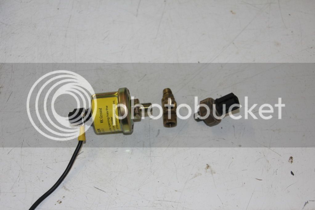
IMG_1300.jpg


Secondly, Now fit the brass block fitting with the Nissan oil pressure sender unit to the engine block using a 6inch shifter (don't oven tighten) Then fit the aftermarket sender unit at the end of the brass block fitting facing towards the drivers side guard.
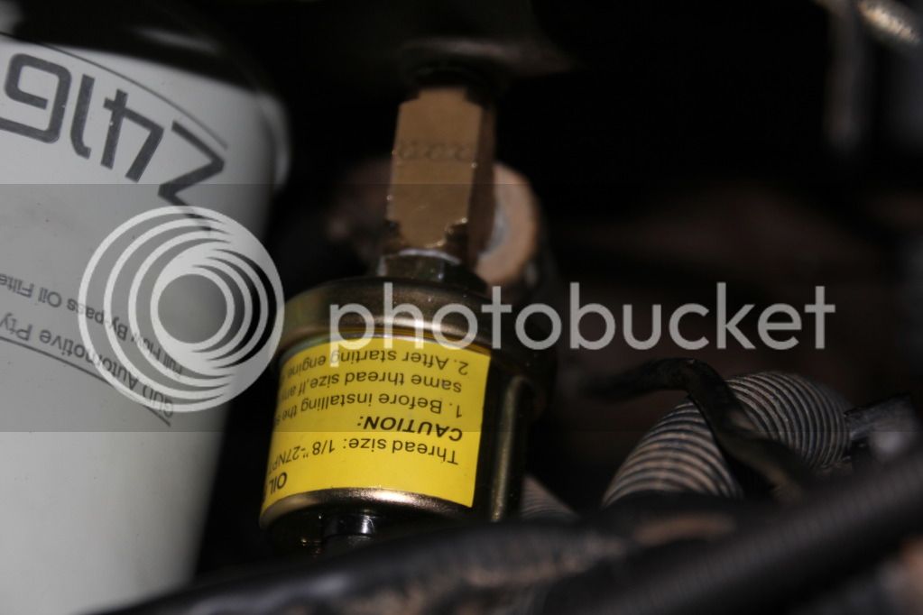
IMG_1302.jpg


Remove factory plug from thermostat housing and Fit water temp sensor fitting here. Remember to use thread tape! If your fitting will not fit, go to your local Pirtec store with thermostat housing and your sensor, so you can fit a reducer two way fitting.
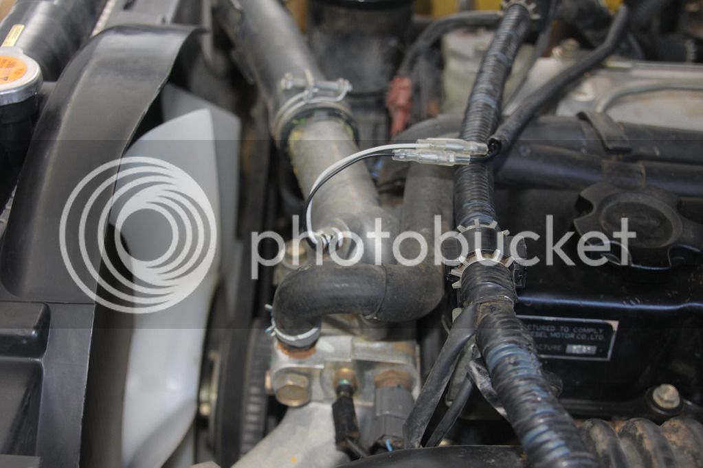
IMG_1376.jpg


more to follow over!
 
Boost fitting!

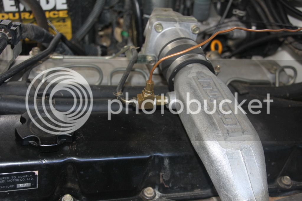
Run copper line through fire/wall into dash area. Tap into boost line on manifold from inlet side of turbo.

IMG_1377.jpg


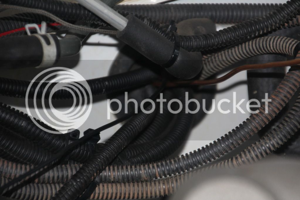
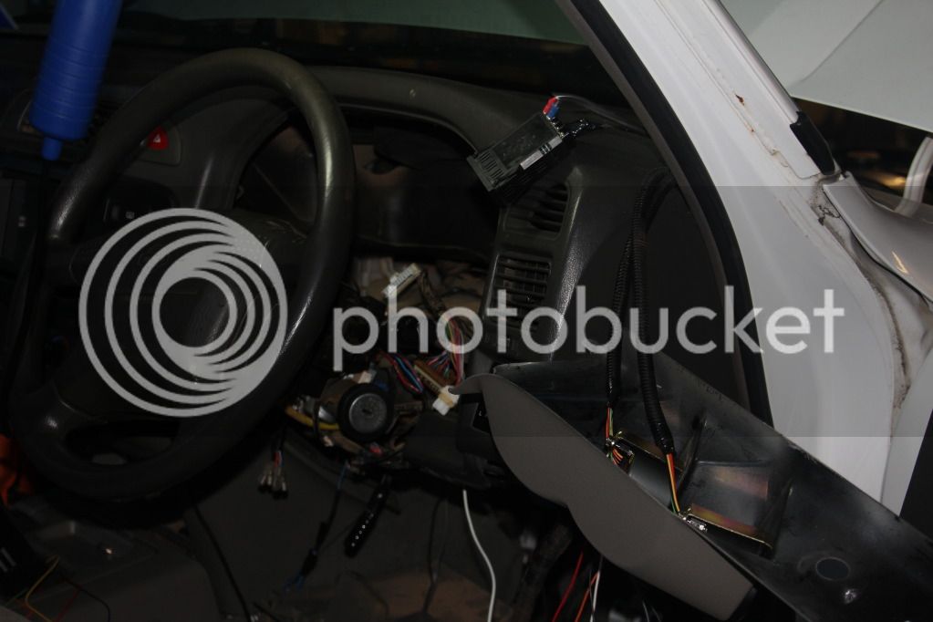
Run all wiring and lines ie, Boost, Dual battery monitor, EGT, Oil pressure and Water temp through this spot in the fire/wall. I like to use flexible conduit to help protect my wiring.

IMG_1388.jpg


Wiring:

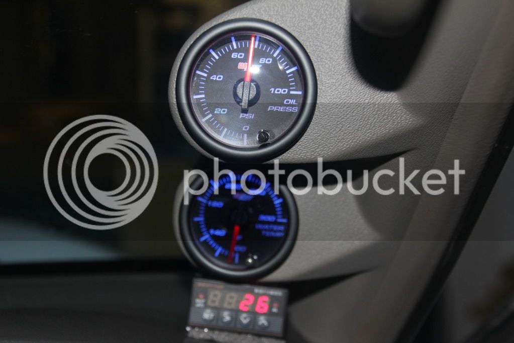
Black wire goes from neg terminal on the back of the aftermarket oil sender unit to the negative terminal on the battery. White wire goes from remaining terminal on the back of the aftermarket sender unit back through drivers side firewall up into pillar pod into terminal clip to gauge.

Water temp the same. Run EGT wiring from dump pipe through fire-wall as with previous wires. Same goes for Boost line.

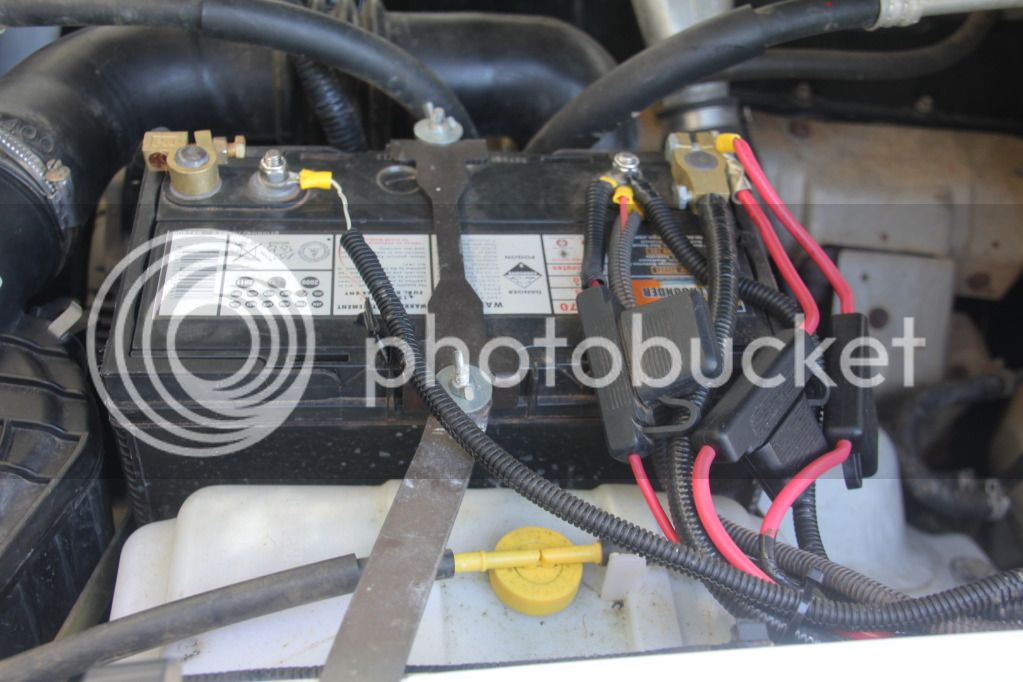
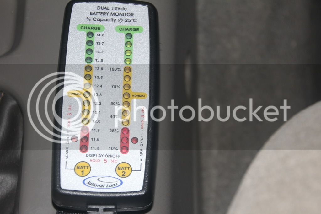
Dual battery monitor wiring. Battery 1, fit black wire to neg terminal. Fit red wire to positive terminal. Remember to fit a 3 amp inline fuse to both positive wires to the battery terminals. Battery 2 the same as for Battery 1. Note: You will have to solder extra lengths of additional wiring to the dual battery monitor loom.

IMG_1378.jpg


more to follow over!
:rambo:
 
INSIDE THE CABIN:

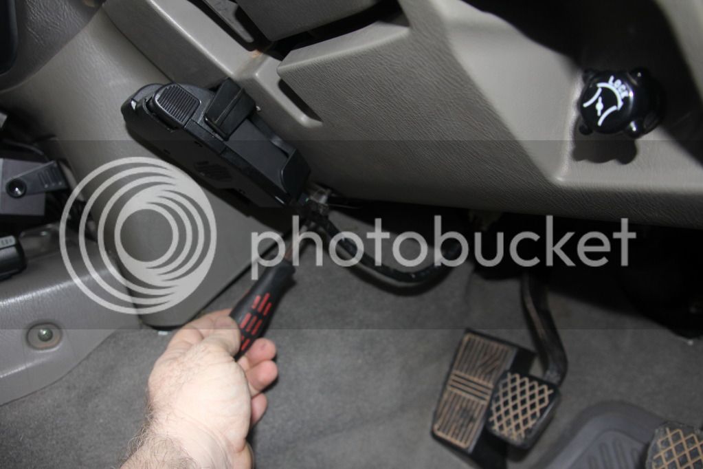
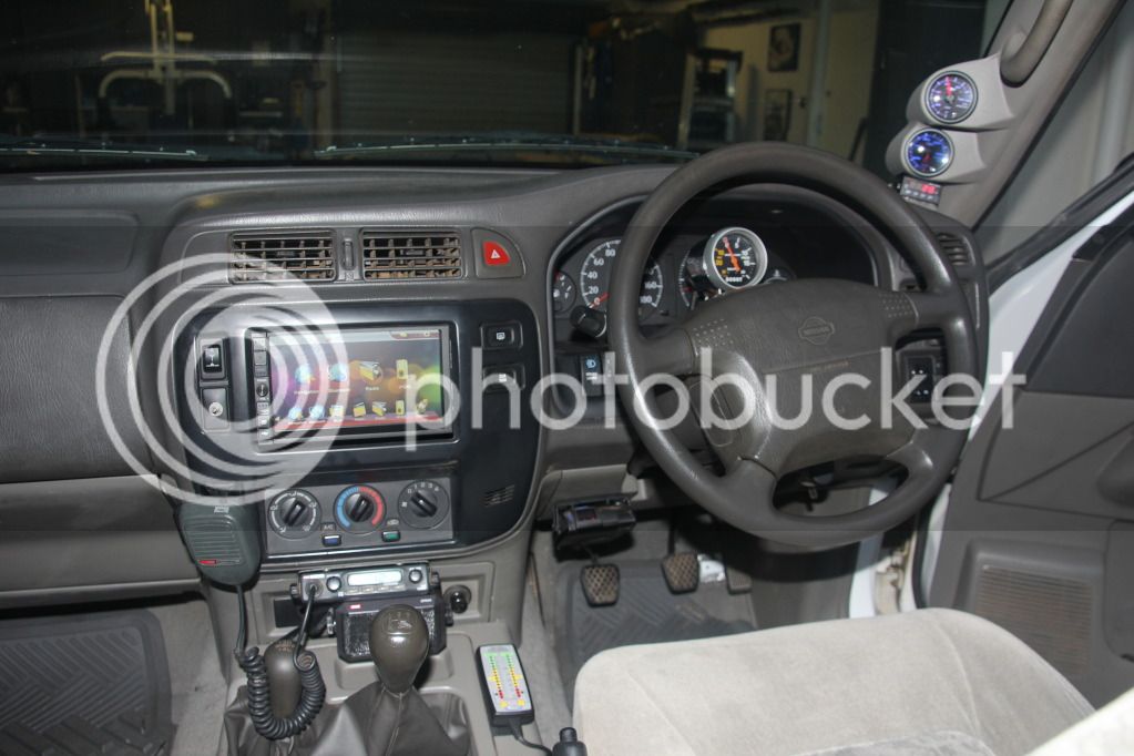
Firstly, we need to get access to our areas of operations ie; pillar Pod, under the dash and the cigarette lighter area. To access the pillar Pod area, using a Phillips head screw driver remove the grab handle on the drivers side! Now Grab the pillar trim at the top and gentle pull back towards you, with the blade of the screw driver now lever the trim free from the mounting clips. Now look at the following photo, using a 10mm small socket or large Phillips head screw driver we need to remove the both the bonnet and fuel cap release latches.

IMG_1409.jpg


Now remove the following screw, see photo.

IMG_1417.jpg


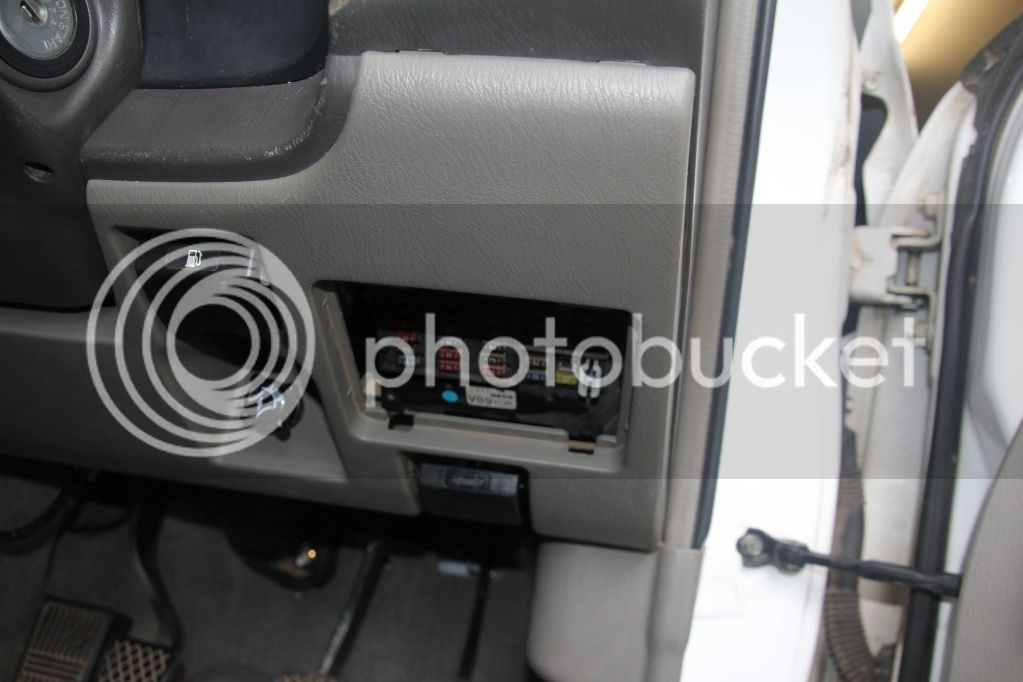
Now remove fuse panel cover, see photo.

IMG_1410.jpg


more to follow over!

:saberfighting:
 
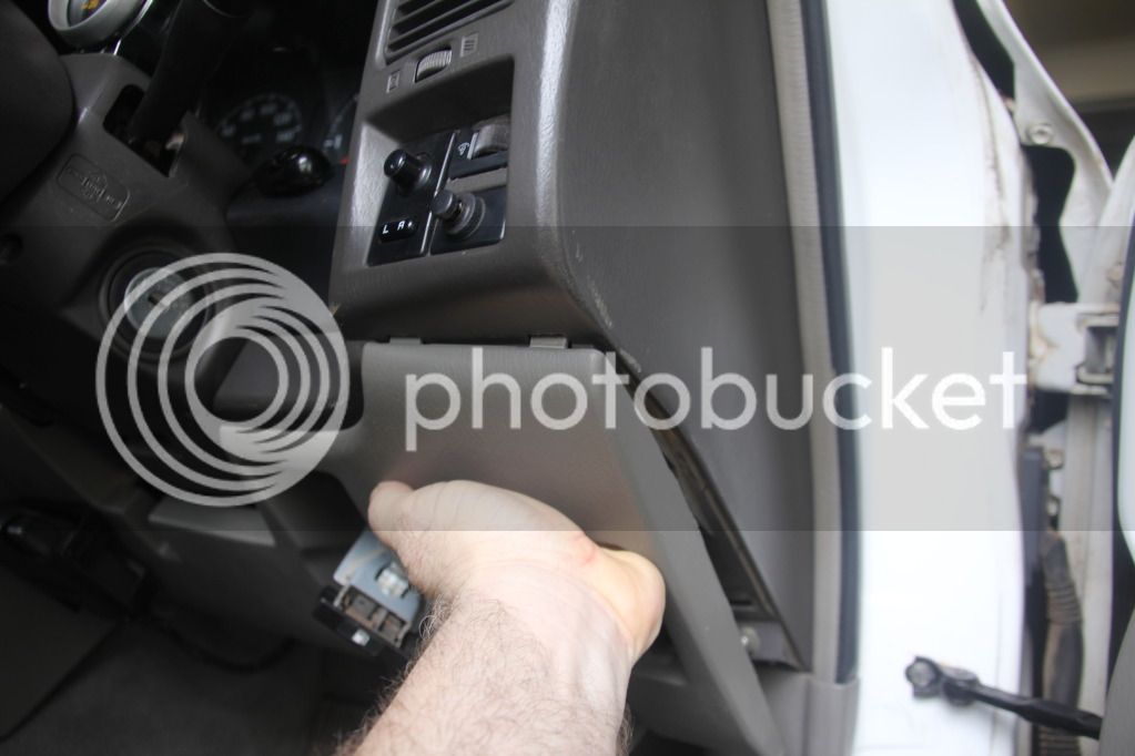
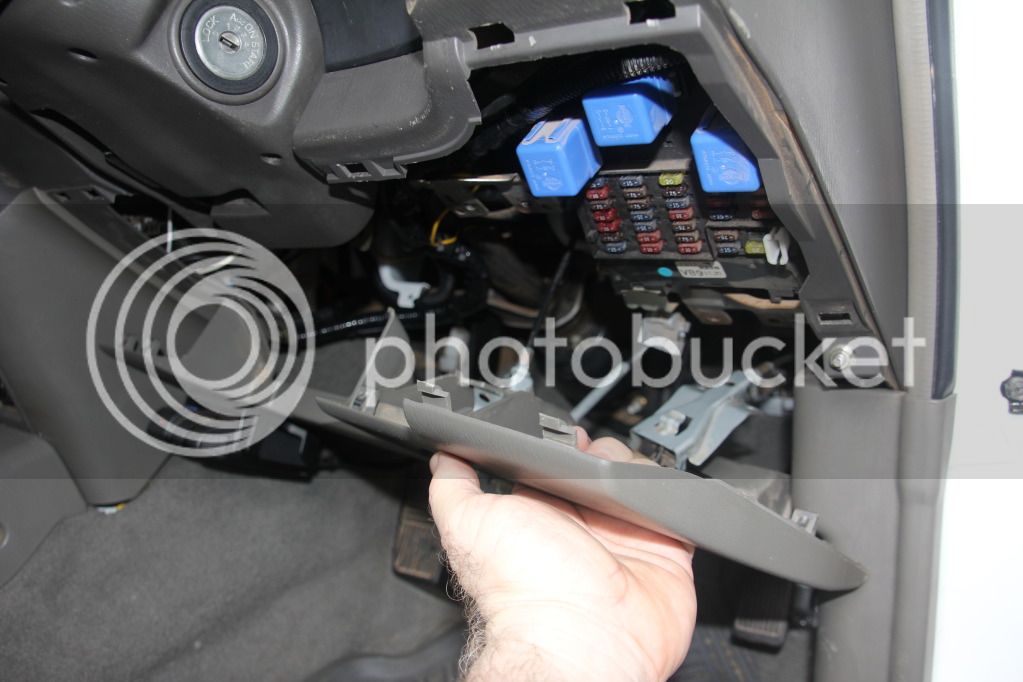
Now place you hand into fuse panel area and gentle grab and pull down and out towards you, this will release this panel so you now have easy access area to work with.

IMG_1412.jpg


IMG_1413.jpg


Now you should have access to both pillar and dash areas!
IMG_1335.jpg


more to follow!
:rambo:
 
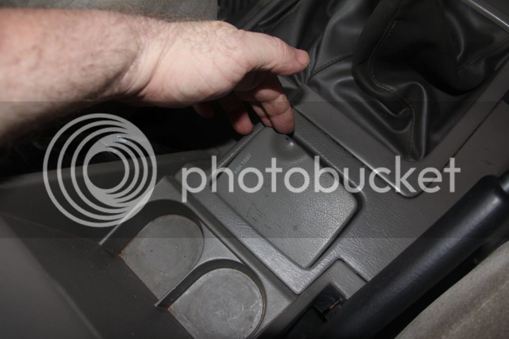
Now remove the ash-tray from the center consul.

IMG_1419.jpg


With the ash-tray removed, use a small Phillips head screw driver to remove the screw! see photo

IMG_1420.jpg


Now remove the two small screws at the front of the consul using a small Phillips head screw driver! see photo

IMG_1418.jpg


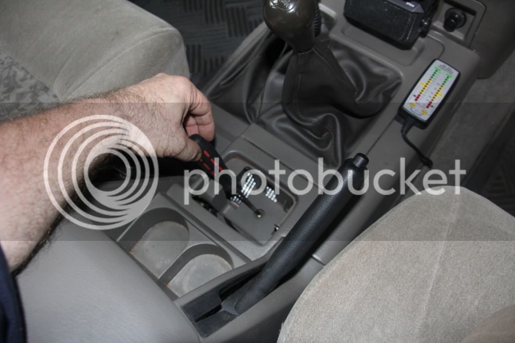
Now remove both the transfer lever and gear-stick knobs. Gentle lift the panel up enough to access the ashtray light connector. disconnect by gently depressing the middle of the connector and pull the two apart. Now remove this panel.

more to follow over!
:rambo:
 
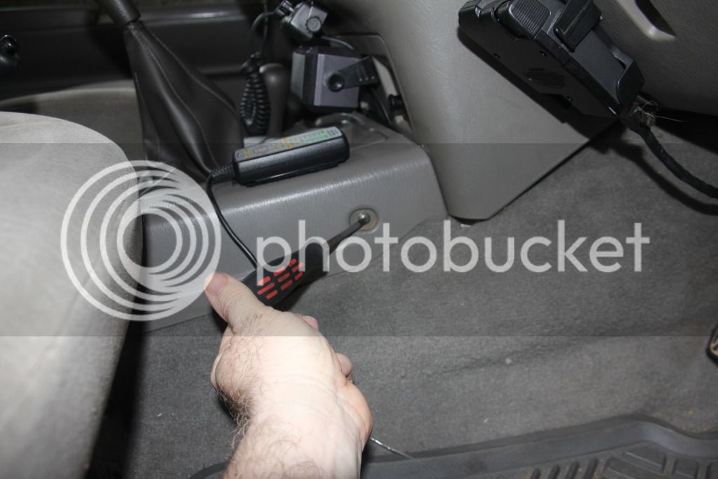
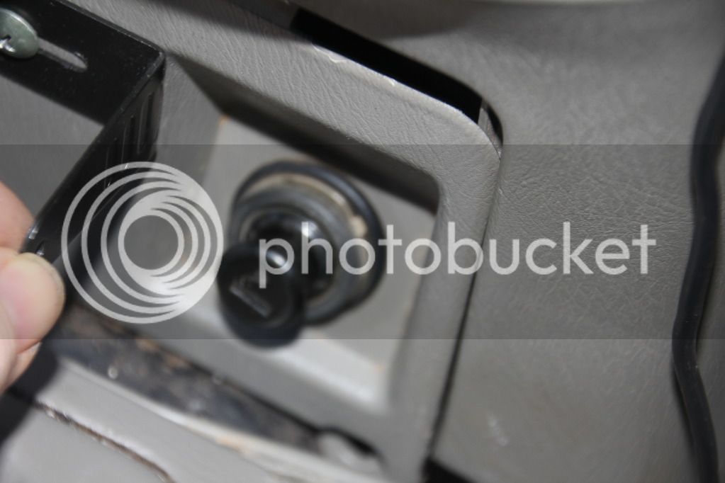
Now undo the two small screws at the bottom of the cigarette lighter panel. Gently pull down on the panel and now you have access to all you working areas.

IMG_1327.jpg


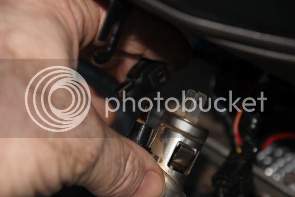
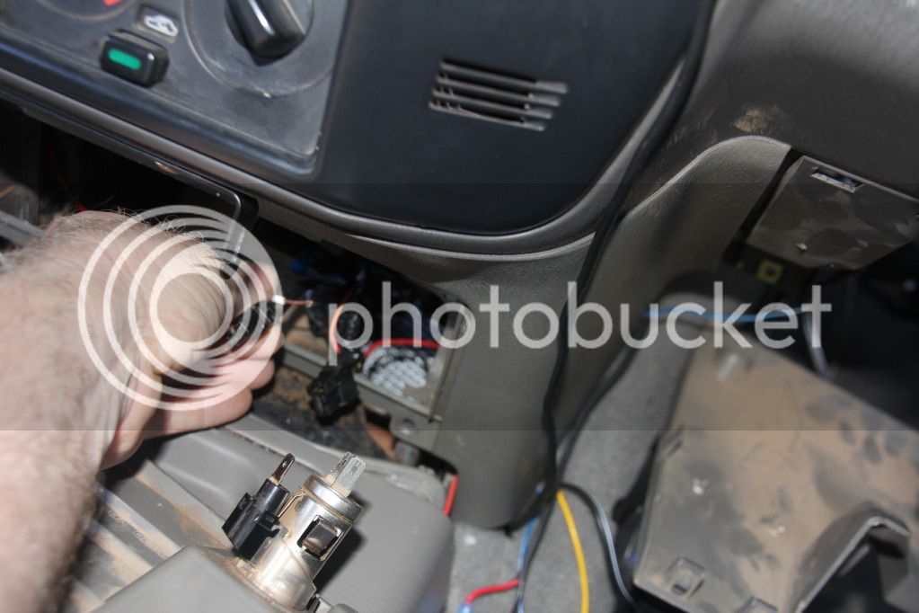
Disconect both the light and cigarette lighter connectors see photo

IMG_1328.jpg


The following are where you are going to splice and solder your wiring from your gauges into. Firstly, wiring from Boost, Oil and Water temp lights will be spliced and solder into the Cigarette light wiring. Secondly, the light wiring for the EGT will be spliced and solder into the Cigarette housing wiring loom.

IMG_1331.jpg


more to follow over!
:rambo:
 
Wiring continued:

From the oil gauge and water temp in the pod. (you may decide to run your Boost and EGT gauges from the pillar pod) Run both red positive wires down though and under dash to light connector on the cigarette lighter. Now splice the wire. Do not solder until you have the Boost (white wire), Oil and Water temp (Red wires) run to the light connector on the cigarette lighter.

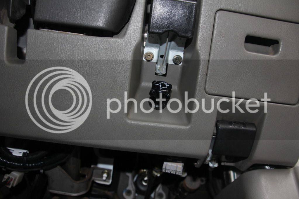
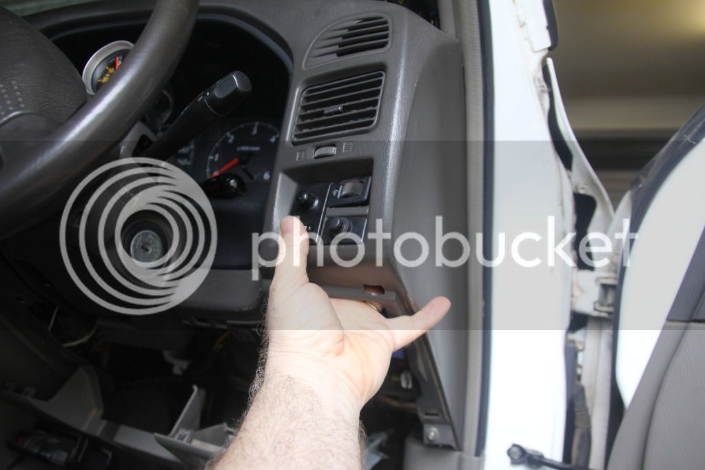
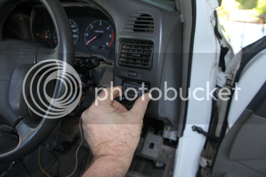
Now pop out the dimmer switch out, see photo;

IMG_1414.jpg


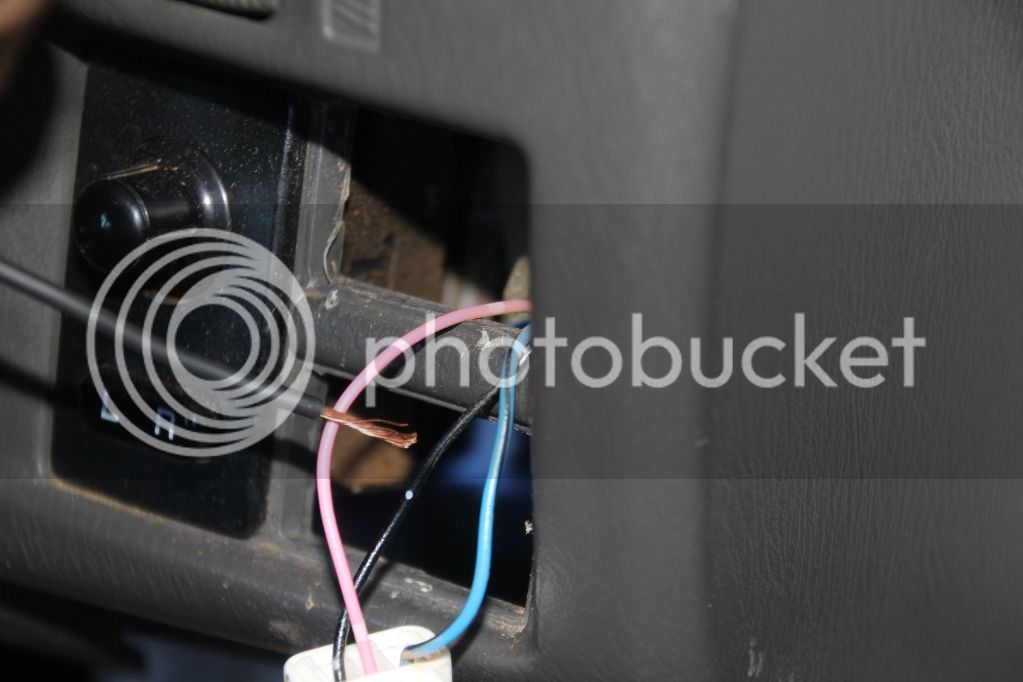
IMG_1325.jpg


With the dimmer switch removed, Splice the 3 black wires from the Boost, Oil and Water temp gauges lights into the pink wire that goes into the dimmer switch (Not the blue wire) See photo below. This now allows you to operate you new gauges lights only at night time when you turn on your head-lights. By wiring into the dimmer switch, you have the additional ability to dim you gauges, if you do not like bright lights.

IMG_1326.jpg


With your EGT gauge light, Red wire goes to Cigarette lighter wiring, your black wire goes to earth on the body. When you turn your ignition on you have a lights at the EGT all the time.

Walla you goat stroker's, you've done it! Now go and have that beer and or any other stress relieve beverage that you usually drink!

Regards,

RLI
:rambo:
 
G'day RLI,
I found these on ebay recently. mini blade fuse adapters.

You might find them useful for all the extra elecs your adding.
 

Attachments

  • IMG_0373.JPG
    IMG_0373.JPG
    94.3 KB
G'day RLI,
I found these on ebay recently. mini blade fuse adapters.

You might find them useful for all the extra elecs your adding.

G'day mate!

Thanks for the heads up on those mini fuse adapters, they look like a great piece of kit!

Regards,

RLI
:rambo:
 
G'day lounge lizards!

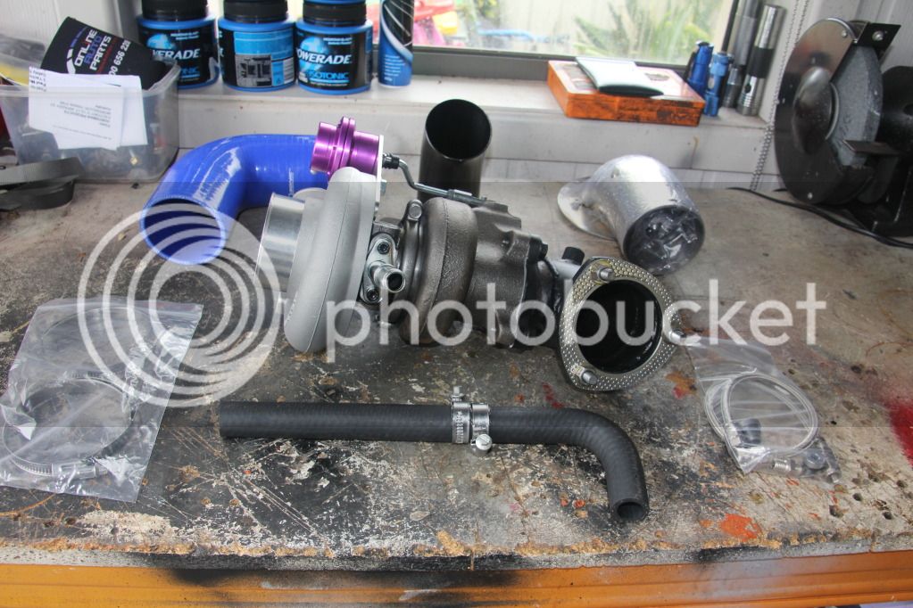
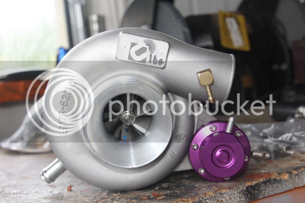
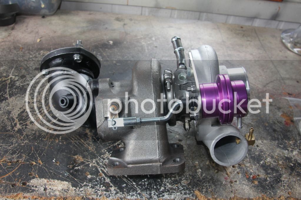
My baby has arrived! My united TD05 18G turbo! Ye-Haa baby!!!!!!!!!!!!!!!!
IMG_1389.jpg


IMG_1390.jpg


IMG_1391.jpg


I cannot wait until i get both the Cross Country intercooler and this baby installed!

Regards,

RLI
:rambo:
 
Good looking build there mate. Looks familiar to another Im watching. Keep up the top work and keep using them quality parts.
 
G'day Lounge Lizards!

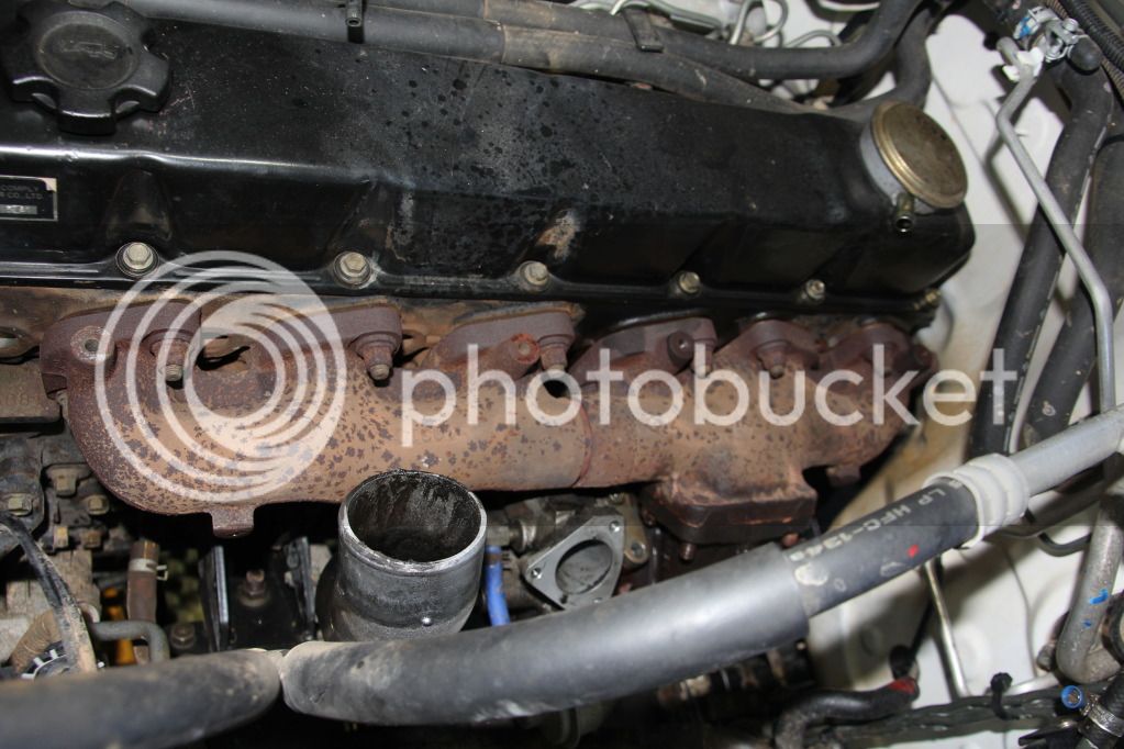
Stated phase 1 this afternoon! Pulled the old factory turbo off! Will post step by instructions soon!

IMG_1529-1.jpg


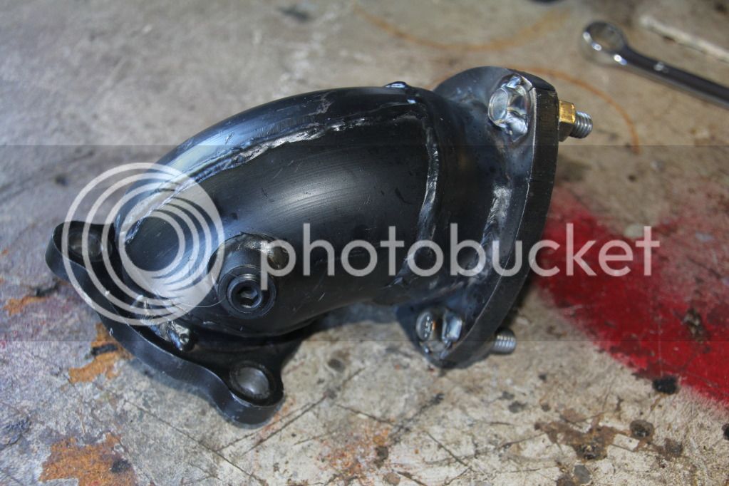
Took your great advice newby (Killer-Wasp!) I went to my mates shed in Coffs and welded the dump-pipe bolts to the dump pipe!

IMG_1503.jpg


Removing the old shite factory turbo!

IMG_1518.jpg


MORE TO FOLLOW OVER!

Regards,

RLI
:rambo:
 
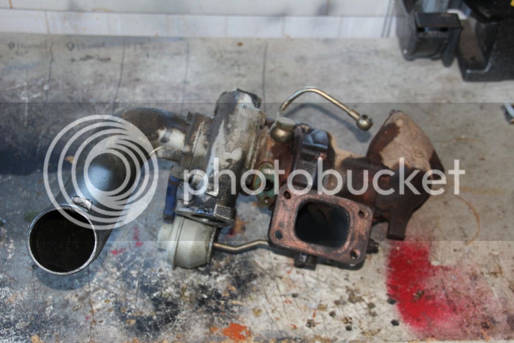
Old one on the bench!

IMG_1526.jpg


Big difference between the new TD05 16G inlet housing and the old factory turbo inlet housing!

IMG_1535.jpg


Fark-yus! 6.00pm is drinking time! You will have to wait until tomorrow Trendsetters!

IMG_1533.jpg


Regards,

RLI
 

Latest posts

Back
Top