Wiring Diagrams

Nissan Navara Forum

Help Support Nissan Navara Forum:

This site may earn a commission from merchant affiliate links, including eBay, Amazon, and others.
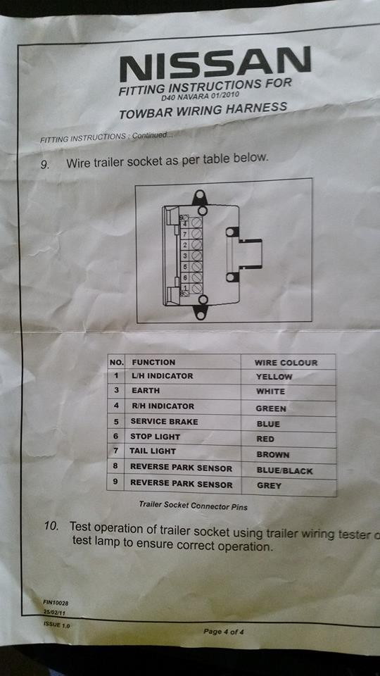
KGKP0uH.jpg


Trailer plug Vehicle side
 
That's a very handy one. It would be a good thing to start getting some of the factory wire colours that are used in som installations.
I will put up some of the ones I've used when I get to pulling some covers off to have a look.
 
Fitted a Steinbauer chip today and found the black wire in the pedal plug is the control wire for the D22 YD25.
 
Glow plug circuit

Gday mate.
Have a glow plug fault. Not the relay or plugs. Can u access a glow plug circuit. Or even locations of everything. Chasing the control module. 2012 2.5L crd. Cheers
 
Gday mate. Have a glow plug fault. Not the relay or plugs. Can u access a glow plug circuit. Or even locations of everything. Chasing the control module. 2012 2.5L crd. Cheers
I think the glow relay is under the bonnet behind the drivers side battery in the grey box. It should say what's what on the top cover. I think the navara system is very basic. Get someone to turn the key and have a listen, you should hear it click. Just be aware that when you shut the key off and I think it only does it when the engine has been running, you will hear the EGR valve doing its thing. I have a diagram it and I will see what info I can find for you.

Cheers Brad.
 
Cheers for the reply. Yea ive found the relay. And the fuse is blown. Ive tested the glow plugs and they have .5 ohm on them all. And the relay functions with jumper wires. Ive tested the power wite leaving the relay and it has a dead short on it. With the glow plugs disconnected. I want to find where that power wire goes so i can unplug it and prove the cable. But there was a bad electrical smell so im thinking that the module have thrown it in
 
If you are looking for a reverse trigger you will find one under the drivers seat. I will update the wire colour once I confirm it. For now it can be found in plug 112 or 121 in the diagram below.

image-672719985.jpg

If anyone has found the wire and can confirm its colour. Feel free to post it.
 
If you are looking for a reverse trigger you will find one under the drivers seat. I will update the wire colour once I confirm it. For now it can be found in plug 112 or 121 in the diagram below.

View attachment 16841

If anyone has found the wire and can confirm its colour. Feel free to post it.

What does it plug into?
If not found I will try and find it when I get home from this swing. At least now I have a starting point.
 
What does it plug into? If not found I will try and find it when I get home from this swing. At least now I have a starting point.
112 & 121 plug into the harness that goes through the floor and back to the rear of the truck, tail lights etc.

image-852277536.jpg

C2 and C9 connect to 112 and 121

Cheers, Brad.
 
Last edited:
getting a pulse from the speedo or ABS

Hi Guys, I am involved with rallying and my 2009 manual D22 is my new survey vehicle. Previously we have fitted senders to the other vehicles via the Speedo cable or a wheel pulse probe. From the little bit of research I have done I believe I can't fit either of these and was wondering if anyone else has taken a pulse form the pulse wires and was it consistent enough to use for survey work.
Cheers in advance
 
An ampere meter can be done three ways.

Using a digital multimeter you can measure up to 10A. Set the meter to 10A, plug the black lead into COM and the red lead into 10A. Disconnect the positive lead to your device (example, a light bar) and touch the red tip to the wire going back to the switch and the black lead to the wire attached to the light bar. Turn on the light bar and the amount of power drawn will be displayed. Warning: this only works for devices that use less than 10A (120W). A single 100W driving light should draw about 8.3A.

Using a clamp meter you can measure currents usually up to around 400A (the one I linked to can measure to 1000A). Just switch it on, turn the knob to 1000A, place the clamp around the cable that you're measuring and read the display. Easy, non-invasive but not highly accurate - it's good as a guide if you're measuring with in a couple of amps, but if you're measuring milliamps go for the previous meter.

Lastly you can use a shunt. This is usually for permanent installations, and they don't like to have long cables to the display - keep them under about a metre. The one I linked to is typical - has a limit of 100A - but you can get larger. These will always display the volts and amps unless you incorporate a switch in the larger red lead. They usually include a wiring diagram to help with installation but they're often in a broken English. If you're relatively new at electrics getting some help is valuable but if you like tinkering then go for it. Basically they read the voltage on the battery at the terminals, then ALL negative power runs through the shunt and another wire attaches to the other side of the shunt, which tells the circuit how much the voltage dropped over the shunt - and using Ohms law, you can then work out how much current is flowing.
 

Latest posts

Back
Top